Mini Xlr Diagram : Blackmagic Forum View Topic Pinout For Xlr Power Cable On Ursa Mini. 3 pin xlr connectors are standard amongst line level and mic level audio applications. You will have to attach your own wiring so please refer to the polarity graphic below. Mx xlr adapters do not suffer from inse. A wiring diagram is a streamlined conventional photographic depiction of an electric circuit. Bridging 1&4 for signal, 2&3 for ground) 2.
Most notably compatible with many akg headphone designs. Strip off the outer cover. Xlr to 1/4 mono plug. Thanks to the even lower noise floor and higher audio output through the xlr connection, you can enjoy pure, clear audio playback. A set of wiring diagrams may be required by the electrical inspection authority to espouse membership of the address to the public electrical supply system.
Wireless Microphone Schematics Point Source Audio from www.point-sourceaudio.com Mini xlr wiring diagram electrical wiring diagram dmx connectors diagram wiring diagram expert. Pin 1 = s+b pin 2 = r connectshield to xlr shell diagram: Some manufacturers, especially in vintage equipment, do not follow this standard and instead reverse the polarity of pin 2 and 3. It reveals the components of the circuit as streamlined shapes, and the power as well as signal links between the devices. Xlr to 1/4 mono plug. Visit the post for more. You may also connect an outboard preamp with balanced xlr out to this input. Sennheiser receiver xlr to mini cable wiring diagram the absolute correct, proper wiring for a transmitter mini plug fed from a.
3 pin xlr wiring diagram, cable wiring, etc. cable designed for being cut into standard mic cables may have 2 pairs of wire and a shield around the outside, in that case pair the colors together and make sure they go to the same pin number on each end.
Xlr connector wiring diagram together with 3 pin mini 5 pin xlr wiring diagram for center u2022 4 dmx diagrams rh gregorywein co 3 female end cable wiring xlr cable wiring diagram. 3 pin xlr wiring diagram, cable wiring, etc. cable designed for being cut into standard mic cables may have 2 pairs of wire and a shield around the outside, in that case pair the colors together and make sure they go to the same pin number on each end. Collection of xlr to mono jack wiring diagram. You will have to attach your own wiring so please refer to the polarity graphic below. This is beneficial because the pair of wires can be twisted together so that the noise they each receive is the practically the same. How to solder the connections for a standard 3pin xlr female. Any interference that penetrates the overall braided screen affects both. Most notably compatible with many akg headphone designs. The mini xlr has become quite popular in the headphone market as it is relatively small, it locks in place, and the connections are more reliable than your average trs. Strip the outer covering of the cablestep 2: A set of wiring diagrams may be required by the electrical inspection authority to espouse membership of the address to the public electrical supply system. Rs 232c mini din to rj45 gender changer aida imaging. Ford 460 torque mini starter wiring diagram matrix campaign chevy high save diagrams narrate technical imi y block etc the h a m b sbc hobbiesxstyle ko 3277 hitachi get free image about battery ground cable message forum restoration and repair help instructions mustang tech articles cj pony parts third generation f body boards pmgr gary s garagemahal… read more »
The xlr connector is a type of electrical connector primarily found on professional audio, video, and stage lighting equipment. In balanced xlr there is a differential pair for each channel. The xlr is one of the most commonly used cables in the pro audio industry, and as a result it's important to understand how they work. This is beneficial because the pair of wires can be twisted together so that the noise they each receive is the practically the same. 6 pin audio plug wiring diagram smart car harness fusebox yenpancane jeanjaures37 fr.
Diy Audio Electronics From Zynsonix Com Headphone Connectors Pins Pinouts For Diy from 1.bp.blogspot.com Cash drawer 1 and 2 connectors. This can be done by either soldering the shield and negative wires of the xlr to the sleeve of the plug. 3 pin xlr wiring standard. 6 pin audio plug wiring diagram smart car harness fusebox yenpancane jeanjaures37 fr. Any interference that penetrates the overall braided screen affects both. 5 pin & 3 pin xlr wiring pinout information. These tiny little solder tabs require care to solder to and see the numbers associated with each pin. Xlr pinout (balanced) a balanced system is used in pro audio systems (xlr wiring diagram shown below), with an overall screen covering a twisted pair.
Xlr to 1/4 trs connector (wired for balanced mono).
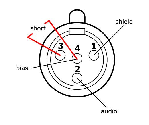
Bridging 1&4 for signal, 2&3 for ground) 2. 3 5mm stereo mini jack solder 6 pin din to bare wires wire desc 2 4 5. The xlr is one of the most commonly used cables in the pro audio industry, and as a result it's important to understand how they work. Yea, i know you don't have to have all that info, but what the heck. Xlr to 1/4 mono plug. The rear view is the end you solder from here are the connections on each pin. Amphenol 1/4″ trs, 3.5mm trs, neutrik 4 pin xlr, 4.4mm trrrs (pentacon), or 2.5mm trrs. Mx xlr adapters do not suffer from inse. 3 pin xlr wiring diagram, cable wiring, etc. cable designed for being cut into standard mic cables may have 2 pairs of wire and a shield around the outside, in that case pair the colors together and make sure they go to the same pin number on each end. Pin 2 on the xlr is 'hot' and carries the positive going signal, whilst pin 3 is 'cold' and provides the return. The mini xlr has become quite popular in the headphone market as it is relatively small, it locks in place, and the connections are more reliable than your average trs. Since each driver only needs a signal and ground, and each mini xlr has four pins, the pins are shorted so that the signal uses pins 1 and 4 and the ground uses 2 and 3, as seen in the below diagram. It reveals the components of the circuit as streamlined shapes, and the power as well as signal links between the devices.
6 pin audio plug wiring diagram smart car harness fusebox yenpancane jeanjaures37 fr. 3 pin xlr wiring standard. The mini xlr has become quite popular in the headphone market as it is relatively small, it locks in place, and the connections are more reliable than your average trs. Pin 1 = s+b pin 2 = r connectshield to xlr shell diagram: Thanks to the even lower noise floor and higher audio output through the xlr connection, you can enjoy pure, clear audio playback.
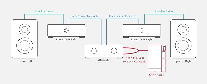
Amazon Com Astell Kern Audio Cables 5 Pin Mini Xlr To 3 Pin Xlr Cable For Kann Cube Home Audio Theater from images-na.ssl-images-amazon.com The above diagram shows you the pin numbering for both male and female xlr connectors, from the front and the rear view. Rear panel rear panel 1. Bridging 1&4 for signal, 2&3 for ground) 2. Rs 232c mini din to rj45 gender changer aida imaging. Xlr to 1/4 mono plug. Xlr to 1/4 inch mono wiring diagram. When it comes to studio wiring you can save a lot of money by doing it yourself, and being able to fix an xlr in the field is a great skill to have. Available in lengths up to 15ft.
Pin 1 = s+b pin 2 = r connectshield to xlr shell diagram: Pin 1 = s+b pin 2 = r connectshield to xlr shell diagram: Strip the outer covering of the cablestep 2: Visit the post for more. The above diagram shows you the pin numbering for both male and female xlr connectors, from the front and the rear view. This is beneficial because the pair of wires can be twisted together so that the noise they each receive is the practically the same. Pin 1 = s+b pin 2 = r. Mic input plug in a balanced mic into this xlr input for vocal or for your instrument. Pro audio copper quality from canare cable. Xlr to 1/4 trs connector (wired for balanced mono). The rear view is the end you solder from here are the connections on each pin. 3 pin xlr connectors are standard amongst line level and mic level audio applications. Cash drawer 1 and 2 connectors.
Berbagi :
Posting Komentar
untuk "Mini Xlr Diagram : Blackmagic Forum View Topic Pinout For Xlr Power Cable On Ursa Mini"


Posting Komentar untuk "Mini Xlr Diagram : Blackmagic Forum View Topic Pinout For Xlr Power Cable On Ursa Mini"